Low impedance HV components are a big challenge when ripple testing
Ripple testing might seem to be like an easy to perform test – but the devil lies in the detail. The biggest challenge is how to reach the required ripple voltage levels at the EUT terminals. And this depends heavily on the impedance of the component.
High voltage components of the drive train (HV battery and inverters) are designed to provide the required energy to accelerate the car. The power is typically in the range of 50kW for small cars and can go up to 300kW for sports cars or even higher for heavy duty vehicles. They are designed for maximum performance and efficiency. Efficiency depends on internal losses, where thermal loss is the dominant factor. Thermal loss is given by the electrical losses P = I2R. In other words, the smaller the (internal) resistance of the component the better the efficiency.
For DC, the DC equivalent resistance is important. For ripple, the AC impedance is more important – seen over the full frequency range that needs to be tested. Here two typical impedance vs. frequency plots of HV components:
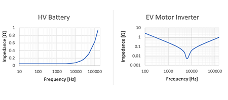
The battery shows a relatively flat impedance curve in the lower frequency range with impedance value in the range of 20 mΩ (very large battery) to 200 mΩ (for smaller hybrid batteries). The impedance increases with higher frequencies to several ohms.
Other components like inverters, chargers or DC-DC converters show a different impedance curve. The minimum at 6 kHz indicates a resonance frequency, which is caused by the input filter of the component. The frequency and steepness of the curve depends on the capacitors and inductors used in the filter. At resonance frequencies, the impedance reaches extremely small values in the mΩ range.
The challenge of the ripple test is seen when the low impedance and the required voltage amplitudes are combined using Ohm’s law:
| FREQUENCY |
IMPEDANCE |
RIPPLE VOLTAGE |
RIPPLE CURRENT |
RIPPLE POWER |
| 100 Hz |
50 mΩ |
24 Vpp |
480 App (170 Arms) |
1,44 kVA |
| 10 kHz |
70 mΩ |
48 Vpp |
685 App (242 Arms) |
4.7 kVA |
| 100 kHz |
600 mΩ |
16 Vpp |
26 App (9 Arms) |
0.05 kVA |
This example shows that very high ripple currents and ripple power is required to reach the voltage levels defined by the standard. Caused by the fact that HV components have very small internal impedance.
It is not in all situations reasonable to test with the highest ripple currents since it might lead to the destruction of the component. Here it makes sense to limit the ripple currents to values that realistically can occur in the car.
If you have a comment or question about this article, please contact us using the form below. Your question will be answered by one of our EMC application experts.